
This page documents my progress throughout the course of TECH 420.
PROJECT 3 - COMPOSITING ANIMATED ASSETS
The primary purpose for this project is to integrate a character or other animated asset using complex deformations into a live action scene. Emphasis for this project is in creating highly polished and believable work. Consider what you want to achieve as you plan for this project. Work must incorporate several of the fundamentals that we've talked about in class. Reference is required, as well as providing your own photography for the background. Camera tracking is also required.
4/30/2020
I am not too familiar with 2D/3D tracking in Nuke. This project will provide a good opportunity for me to learn this skillset. Today I watched some tutorials and experimented with the tracking nodes.
5/1/2020
Today I chose a character and animation from Mixamo. I decided to change my animation from the pitched animation in class on Wednesday because the animation in which the character reacts to the light in the scene does not match the direction. Instead I chose to use a salsa dancing animation loop which I think makes for a funny narrative.
To start off this final project I imported the FBX with animation into a scene in Maya. Because I would liked the ability to modify the textures, I took the time to separated the geometry and tweak the UVs before creating a cache.
Note: For those who are not familiar with animation tools/techniques, a Locator can be created and parented to the rig so that the animation/geometry can be moved/scaled before creating a cache of the geometry. After the cache is created, the rig is no longer attached to the geometry.
Bellow is the character and place I plan on matching for my scene.
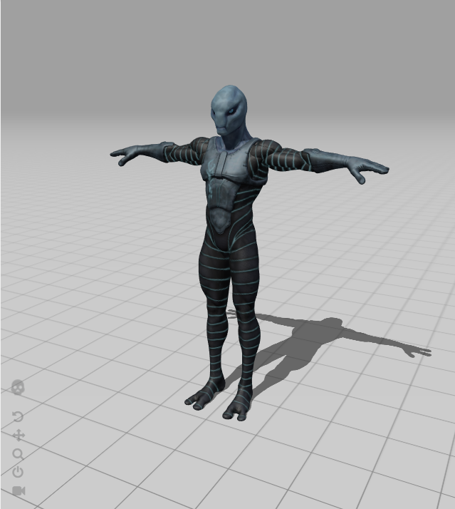
Zlorp

5/3/2020
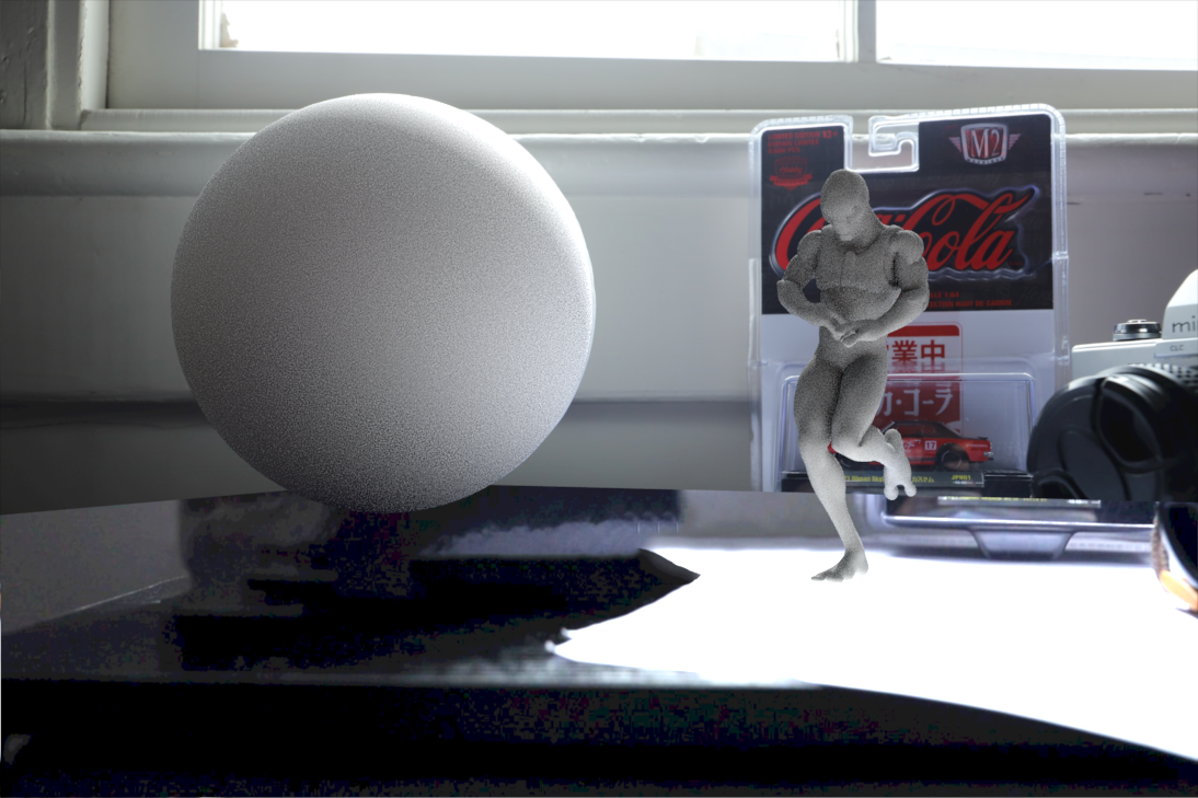
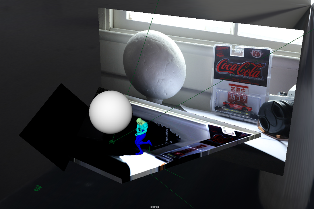
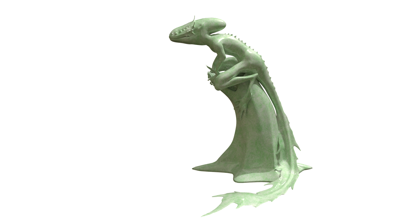
Today the perspective was matched in Maya and a SSS texture map was created in Substance Painter and plugged into the shader in Maya. See images bellow for results.


5/4/2020
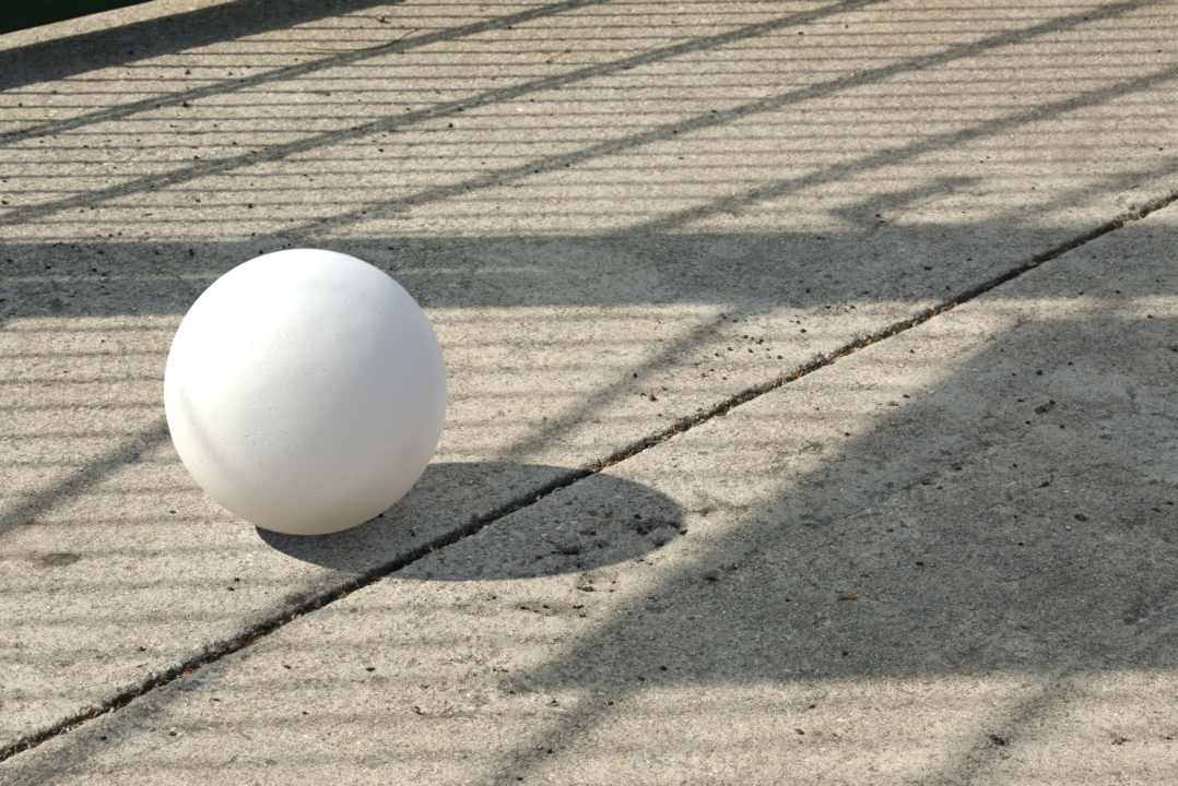
Today the sphere that represents the grey ball in the photo set was created and the lighting was matched.
Potential issue: Getting the proper amount of bounce light reflected on to the grey ball causes the bounce light from the ground to blow out the character. To fix this, the lighting was matched to create what is perceived to be the proper amount of bounce lighting for the character. This will likely need to be tweaked after the final texture maps for the character are applied.

5/5/2020
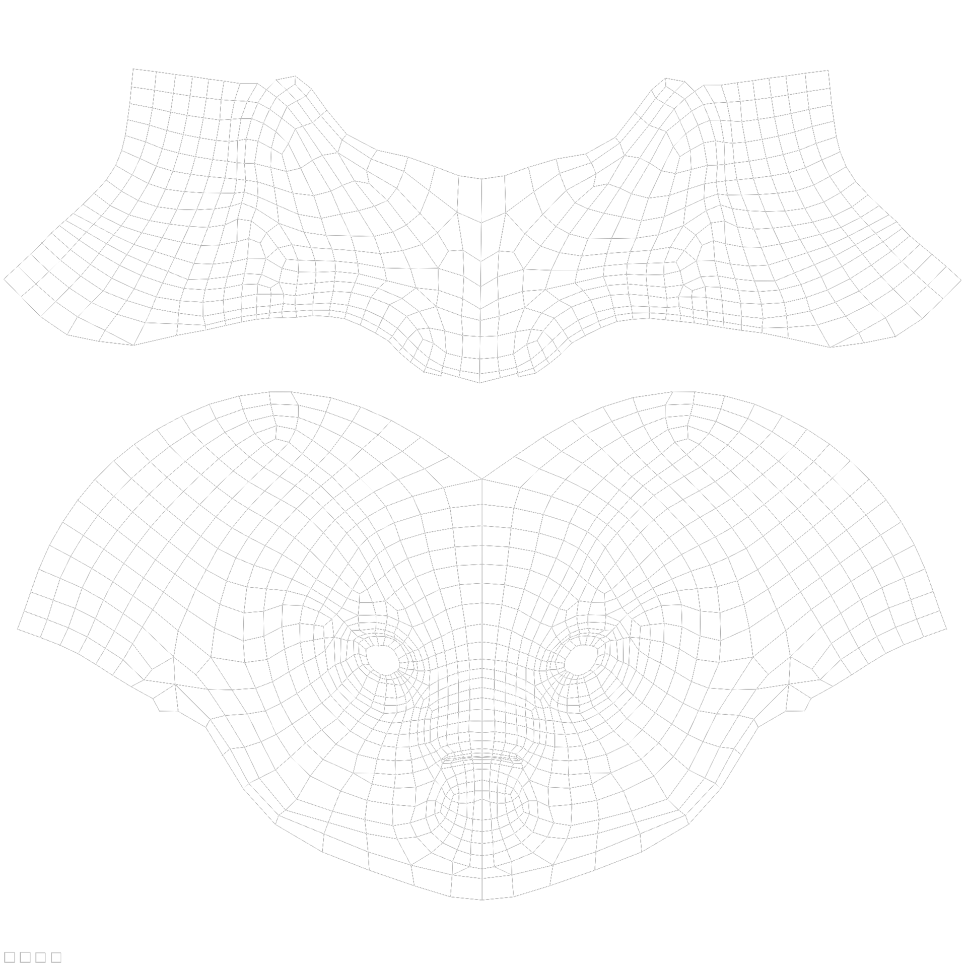
Today the charater's Uvs were modified to get the best textures possible. Most of the UV's for the body have been fairly optimized however the head and eye UV's had to be relaid for optimization. Additionally, the geometry was divided into separate objects, assigned new materials, and laid out in the 0-1 space based on material assignment. This is based on the Substance Painter workflow and can been seen in the image bellow. The colors of the shaders are placeholders to show visual distinction off each bake set until the texture maps get exported from Substance Painter.

5/6/2020
Today, some trouble shooting approaches were discussed in relation to the potential issue posted on 5/3. To fix this issue, a number of factors were modified:
1. It was determined that the HDR being used for the scene was not a true HDR. This being the case, a new HDR was created in Photoshop combining the jpegs of various exposures as outlined in project 1.
2. SSS was added to the shader of the the grey ball in Maya to more accuratently match that of the reference photography.
3. The ground plane was modeled to match the geometry of the desk more accurately. It was also scaled accordingly so that the projection of the surface shader did not repeat in the scene.
4. A gamma projection node was added to the shading network of the surface shader for the ground to modify the values of the image. The image used for the ground projection is not a true HDR and so the gamma correct allows the exposure of the image to be adjusted to the values that need to be adjusted..


5/7/2020
Today, the first attempt at 3D tracking was made. To do this, the original MOV file was brought into Nuke and written out as an uncompressed Tiff file image sequence. After reading the sequence back into Nuke, the frames that will be used for the final shot were identified and set in the read node and project settings.
5/8/2020
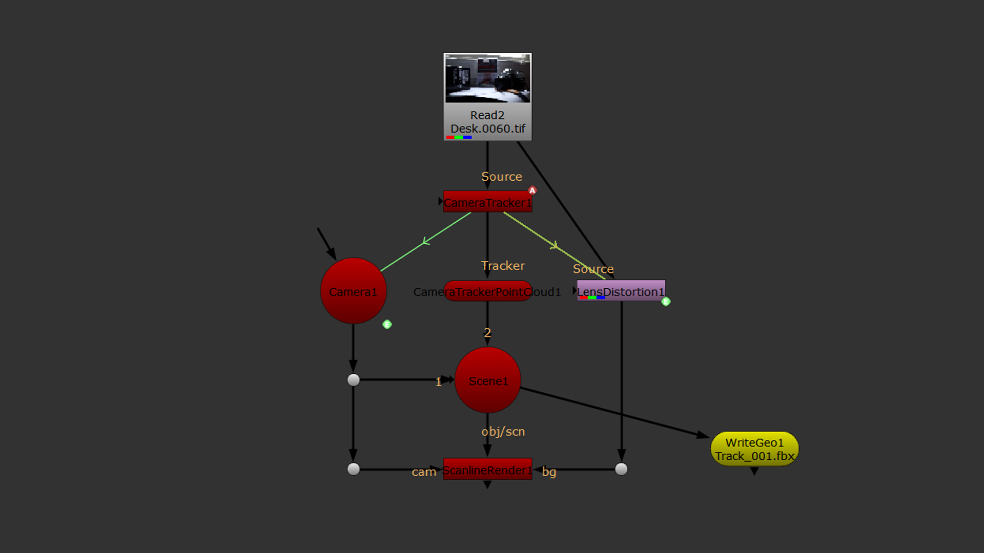
After the image sequence is read back into the composite, create a Camera Tracker node. In the node, set the following:
1. Under the Settings tab, set Features to 150
2. Camera Motion: Free Camera
3. Lens Distortion: 35 mm for this project
4. Film Back Preset: Custom
5. Track the sequence
Note: Avoid specular highlights, reflections, and objects that move when setting a track.
After the track is made the track must be solved. The solve turns the 2D points into 3D. After the solve is created, the tracking points will be green, yellow, or red.
In the AutoTracks tab, Unsolved points can be deleted. Next, various tracking points can be specified. An efficient method of getting rid of most of the red points in the track would be to select track len - min and Min Length in the AutoTracks tab, select a Min Length value (in this case 6). Then Delete Rejected.
Next, update update the solve and check the Error amount in the CameraTracker tab. The goal for an error value should be bellow 1.
After the solve is at an Error value of 1 or lower, it can be exported using Scene+. This creates all of the nodes needed to create a 3D scene.
Finally, create a Write Geo node. This can be used to export the camera from Nuke which will be imported into Maya.
5/9/2020
In Maya, the tracked camera can be imported into the scene. Scale the size of the locators that represent the trackers can and group the tracked camera and locators. Next the tracked camera will need to be scaled and moved to match the cube and geometry already set up in the scene. To achieve this the entire group containing the tracked camera must be moved and scales that way the track does not get broken. This is makes it slightly more tedious to match the perspective because the perspective cannot be matched by transforming the camera while looking through it. This is because the group will not move if the camera is transformed while using this method.
5/11/2020
Today some trouble shooting was done to make sure that the camera track matches the scene correctly. Initially, it was thought that there was something off on the track but the issue was that the track was based on a different frame range than what was set in the project settings. After making this change, the track now works.
Following this, I was able to begin modifying the textures of my character to match what I want for the scene more closely. The UVs for the head have been optimized so the texturing for this part of the model will be done from scratch. However the textures for the body were salvageable so I will be using them as a starting point to get the textures I need for the character.

5/12/2020
Today the tweaked textures were exported from Substance Painter and plugged into the shaders of the Maya scene. Next render layers will be set up and a comp built in Nuke to begin testing the integration of the character.
5/13/2020
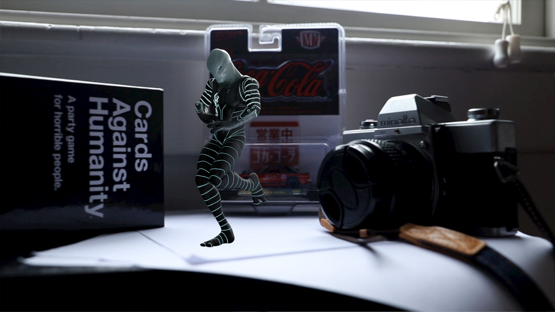
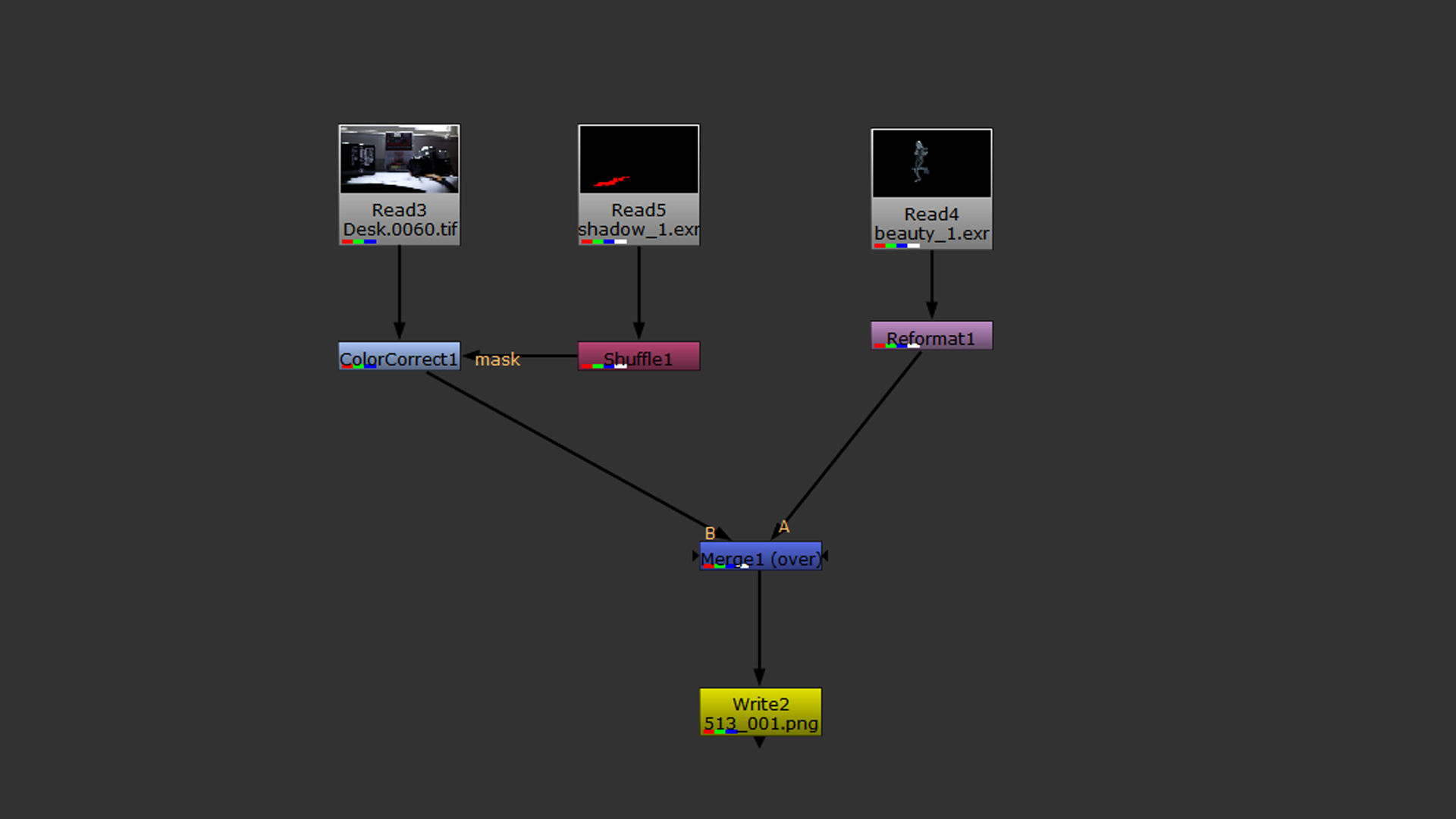
Today I created the Beauty and Shadow render layers in the scene. To get an accurate shadow I modeled some proxy geometry to match that of the edge of the desk and curvature of the paper. Additionally, I tweaked the lighting, specifically the radius of the keylight to more closely match the softness of the shadows in the backplate. See the initial composite and comp tree bellow.

5/14/2020
Today I created the ground occlusion and character occlusion render layers as well as a render layer for the reflection of the character on the Cards Against Humanity box. Currently I am experimenting with the reflection pass in the composite.
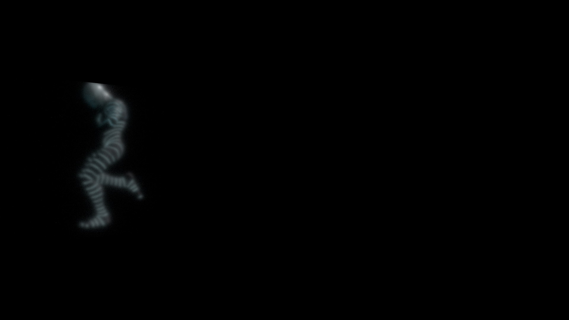
Cards Against Humanity Reflection Layer

Current Composite
5/17/2020
Today, the angle and radius of the key light were adjusted to match the backplate more accurately. Additionally, a Z-depth AOV was added to match the amount of blur in the backplate.

5/21/2020
I have been having issues with my animation on the farm so I decided to just render locally. At this stage, there are two things I would like to address before Sunday:
1. The lip of the paper and how the geometry is affecting the shadow is not in the correct location.
2. I would like to use the motion vector AOV to get a slight sense of motion blur.

5/22/2020
Update: The shadow has been fixed, motion blur has been added, and the reflection on the Cards Against Humanity Box reduced.

5/23/2020
Today I added a reflection of the shadow on the Cards Against Humanity box to better integrate the reflection into the scene.

5/24/2020
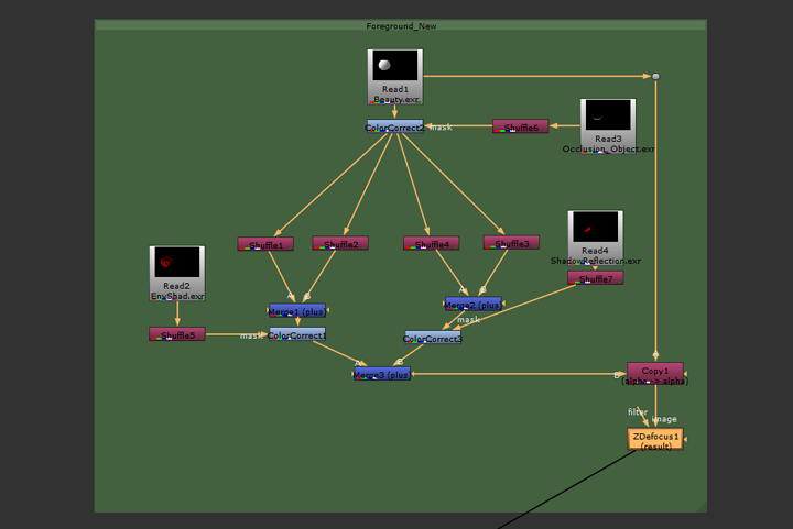
Today I finished compositing my render layers to complete the project. The final comp tree and render sequence can be seen below.

Final Render:
PROJECT 2 - REFLECTION, REFRACTION AND TRANSLUCENCY
Through the use of creating hybrid reflection, refraction and translucency elements in 3D, and the implementation of them, you will further advance your knowledge of integrating elements in compositing. We will explore elements created through the use of Arnold, as well as some additional Maya Software shaders that introduce the concept of reflection and bounce light. Integration is key therefore moving the object will prove that you have accurate integration. Descriptive use of buildup and breakdown elements is required.
4/18/2020
This project will focus on the creation of hybrid reflection, refraction and translucency elements in 3D. Additionally it explores elements created through the use of Arnold. as well as some additional Maya Software shaders the introduce the concept of reflection and bounce light. The goal is to create an accurate integration of a CG object in a live-action shot.
The process of setting up perspective, lighting, and creating render layers are the same as Project 1 so the documentation of Project 2's progress will focus on the creation of the shader in Maya and the integration in Nuke.
Bellow are pictures of a rock that will act as inspiration for the creation of a shader with similar properties.


After the perspective is set and lighting and render layers created, a shader is created and mixed. My main tool for texturing is Substance Painter however for this project I wanted to experiment with using procedural nodes with Arnold in Maya. Bellow is the first attempt at mixing the shader.


Two aiNoise nodes have been mixed and color corrected then piped into the base color and subsurface color. Also, an aiAmbientOcclusion shader is being clamped and used to drive the weight of the scattering. Multiple aspect of the shader need to be tweaked at this point included however I believe this is a good start towards acheiving an accurate match to the real life material.
4/21/2020
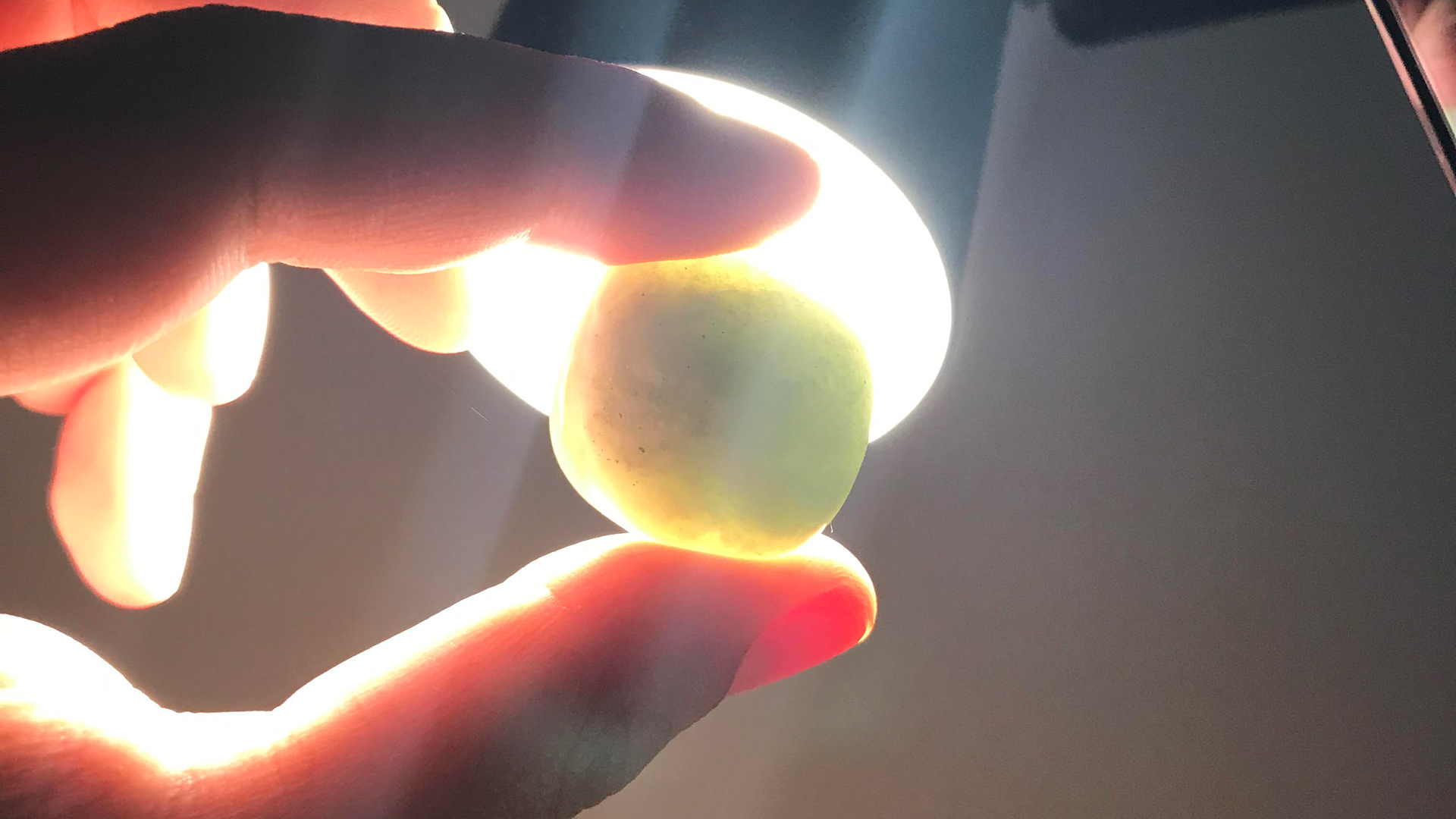
With the creation of new layers specifically for SSS and Transmission, these components can be controlled and rendered separately and composited in Nuke. To get an accurate representation of the amount of SSS and Transmission that needs to be in the shader, the following picture was taken.
Below are the render layers that will be used to composite the different components of the shader. Please note that the sampling has been turned down for the sake of testing. At this point, there are a couple things that need to be addressed:
1. The weight of the transmission in the glass layer needs to be adjusted with some type of map or shader. It looks as if the glass is getting darker in areas where the geometry is thinner.
2. The geometry is made up of displacement maps that take up the same 0-1 UV space. A solution needs to be founds that allows for different displacement maps to be utilized for pieces of geometry that are assigned the same shader.
Note: The aiNoise node, while a texture node, doesn't seem to rely on UV coordinates to create textures on the geometry. This is different than Maya 2D textures that rely on UV coordinates.
Beauty Layer

Transmission Layer - Weight: 1, Extra Roughness: 0.8

Subsurface Layer - Weight driven by aiAmbientOcclusion Shader, Scale: 1, Type: randomwalk, Anisotropy: 0

Fresenel Layer - aiStandardSurface Shader with aiFacingRatio/Ramp plugged into Emission, Diffuse/Specular Weight: 0
4/23/2020
Update: A solution to the displacement issue noted in my last post has been found.
The solution to using the same shader on multiple pieces of geometry and using displacement on only one object is in the Attribute Editor. In the Shape Node, all geometry that is not utilizing displacement in a shader that has a displacement connection should have a height value of 0. This ensures that the displacement in the shader is not affecting the geometry that should not be using displacement. This is an alternative to duplicating the shader to make two versions (one with displacement and one without).
Because utilizing the fresnel mask is a major part of achieving the look of the rock material in the composite, I wanted to experiment and document different methods of achieving this shader in Maya.
Method 1: Using the Maya Surface Shader
Method 2: Using the aiStandard Shader


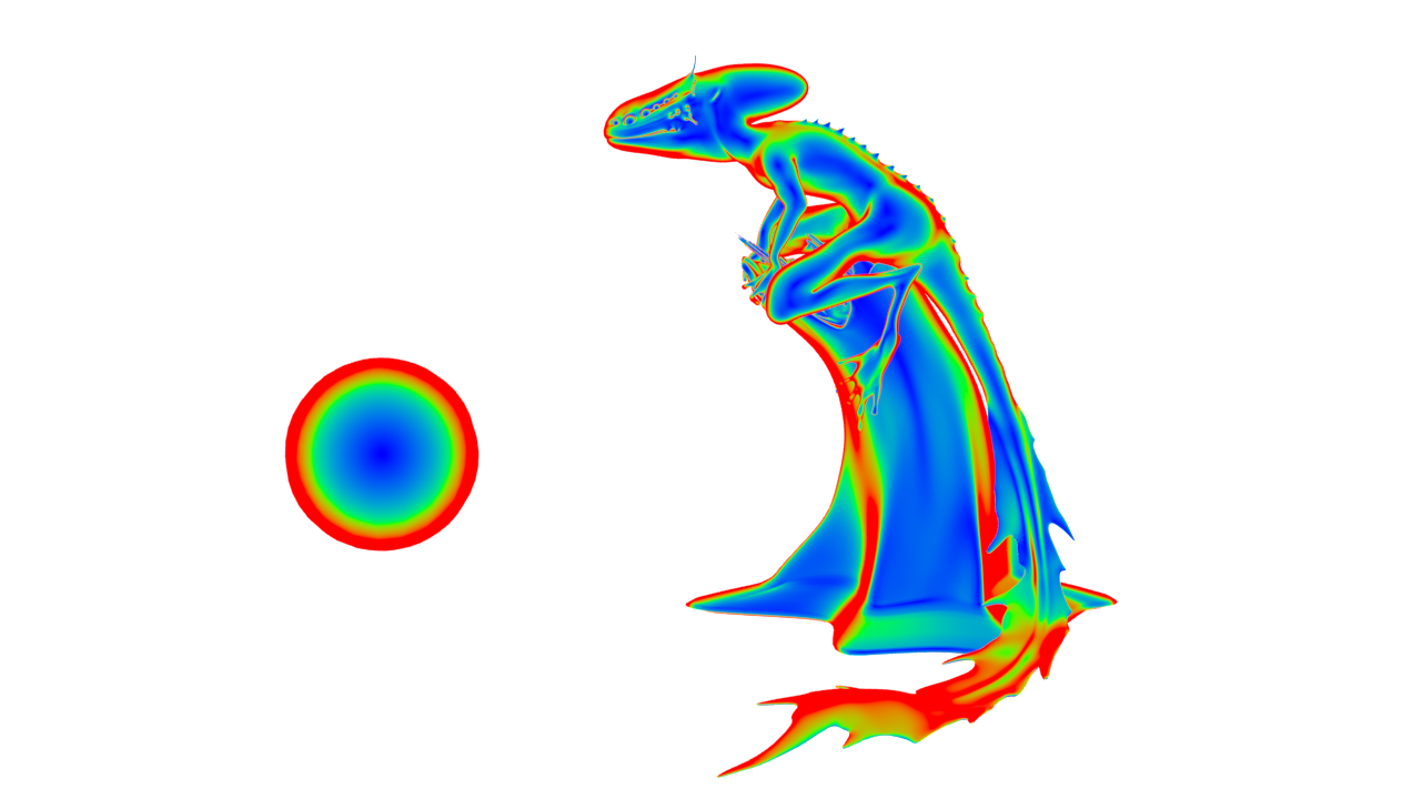
A Sampler Info Node is plugged into the V Coord of a Ramp Node which is then plugged into the out color of the Surface Shader. This creates a ramp of color that remains consist no matter the viewing angle.
An aiFacingRatio Node (Arnold's version of Sampler Info), is plugged into the V Coord of a Ramp Node which is then plugged into the Emission Color of the aiStandard Surface Shader. Emission is the same as Out Color of a Maya Surface Shader which is simply just flat color. This allows the shader to be seen in the render without the need of adding lights to the render layer. This is the preferred method because the aiFacingRatio has the added control of Bias and Gain parameters which allows the falloff and softness of the ramp to be adjusted with more precision in addition to adjusting the ramp itself.

4/23/2020
These two methods of using the facing ratio to create a fresnel mask in this case is so that the transmission and sss can be controlled on separate render layers as well as in the composite in Nuke. However, there is another way of achieving this in a single shader in Maya using an aiMix Shader.

Graph/Work Area Shading Network

Resulting Render
Two separate shaders are combined using the aiMix Shader. The way in which they are mix is determined by the mix input. To achieve the look of the fresnel mask an aiFacing ratio can be used with a ramp just like in Methods 1 and 2. The only differences is that the mix is looking for values between 0 and 1, therefore the ramp must use values between black and white. The red channel can then be used as the input for the mix. The result is a shader with a fresnel effect.
4/27/2020
After tweaking the shaders, rendering the layers, and making adjustments to the node tree, the final result can be seen bellow.

Graph/Work Area Final Shading Network

Final Node Tree

PROJECT 1 - LIGHTING CG OBJECTS THROUGH COMPOSITING
Through the use of creating elements in 3D, you will learn how to control CG lighting by using light and shadow passes with compositing techniques. You will learn how to render 3D elements in layer passes. You will also learn methods on managing elements and naming elements. Your first object for this project is a grey ball that should match the one that is photographed as part of the reference. You will also create an additional (round) object that will represent an item from the real world that has more complex shading such as an orange, soccer ball, or other round object. CG objects will roll through the space and will experience a change in lighting that matches that of the background element. Integration is essential.
3/30/2020
SETTING UP PERSPECTIVE IN MAYA:
1. Create a camera.
2. In the Attribute Editor of the newly created camera, go to to the Environment Tab - Image Plane and link the image containing the cube.
3. Define the scene Working Units in Maya's preferences. In this case, the Working Units should be inches. This should be done BEFORE creating any geometry otherwise the units will be in the previously defined Working Units. (Note: Just like Render Settings, Preferences are on a scene by scene basis.)
4. Create a Cube with the proper measurements.
5. Anchor pivot to the corner of the Cube and snap the Cube to the grid. That way the wold will rotate around that center point.
6. Set resolution of the camera to that of the photograph. After putting in the exact size in with and height, the aspect ratio can be scale with the Maintain with/height ratio option checked. In this case the image is scaled to 1280 x 854.
7. Set the focal length of the camera. If the geometry clips the image plane shape, the depth of the plane can be adjusted.
8. Now the camera can be placed to match the perspective as seen below.

4/4/2020
CREATING THE HDR IMAGE:
HDRI Images can be created in Photoshop by combining multiple versions of the same image with different exposure levels. In Photoshop:
1. Go to File - Automate - Merge to HDR Pro
2. Select all Images (Options: Mode - 32, Remove Ghosts - On, Tone Mapping - Off)
3. Crop image to edges of chrome ball and export as radian.
CREATING THE GLOBAL ILLUMINATION:
After the HDR is created, in Maya:
1. Create a sphere and ground plane and scale accordingly.
2. Create a Surface Shader. In the out color connect map as project by right clicking the File option.
3. Under the Projection Type, choose Ball. This will create one pinch on the sphere instead of two with a seam.
4. Use the projection gizmo to orient the sphere so that the pinch is in the exact center of where the RenderCam is facing.
5. Under the Shape Node of the sphere geometry, under Render Stats, uncheck Primary Visibility and Cast Shadows. Unchecking Cast Shadows will allow the Key light to be place outside of the dome.
A sphere can be created to act as the chrome sphere in the reference to ensure that the HDR matches (AiStandard - Chrome - Base Weight - 0, Roughness - 0, IOR - 200).
CREATING THE SUN/KEY:
Create a Spot Light and place it where the sun is located on the HDR image on the dome. Make sure that the dome geometry does not cast shadows under the Render Stats.
Adjust light color, intensity, and location to match image based on the shadow.
Pro Tip: If Image Plane ever gets distorted, make sure that Fit to Resolution gate is pressed in the Attribute Editor.
4/5/2020
PROJECTING TO THE GROUND PLANE:
This is done to get the accurate color and amount of bounce light into the objects. To project onto the ground plane:
1. Create a Surface Shader. In the out color connect map as project by right clicking the File option. Link the clean plate here.
2. Under the Projection Type, choose Perspective and connect the projection to the RenderCam in the Attribute Editor. This will create a projection based on the ground plane based on the perspective of the RenderCam.
Pro Tip: If Projection does not mach the Image Plane, make sure the Fit Type is set to Match to Resolution in the Attribute Editor.
CREATING RENDER LAYERS:
Beauty Layer - Everything that is in the masterLayer. Primary Visibility turned off on: ground plane, WorldDome, and Image Plane
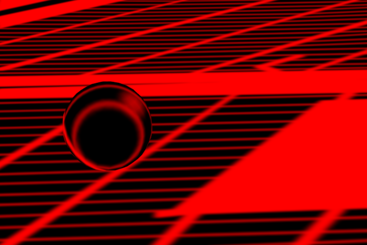
Shadow Layer - Sphere (Primary Visibility turned off), ground plane (aiShadowMatte - shadow color turned to red), and spot light
Occlusion Layer - Sphere and ground plane with aiAmbientOcclusion shader applied (black and white values inversed)
4/7/2020

Current node tree. Note: Clean Plate and Shadow images don't have alphas so auto alpha will need to be turned on.

Problem areas at this point include ambient occlusion being too dark in area that isn't in shadow and the fact that the shadow from the fence isn't being projected onto the ball.
Note that noise is due to low pixel sampling to get renders as quickly as possible during the testing phase.
4/8/2020
CONTROL OF OCCLUSION AND PROJECTING THE FENCE SHADOW:
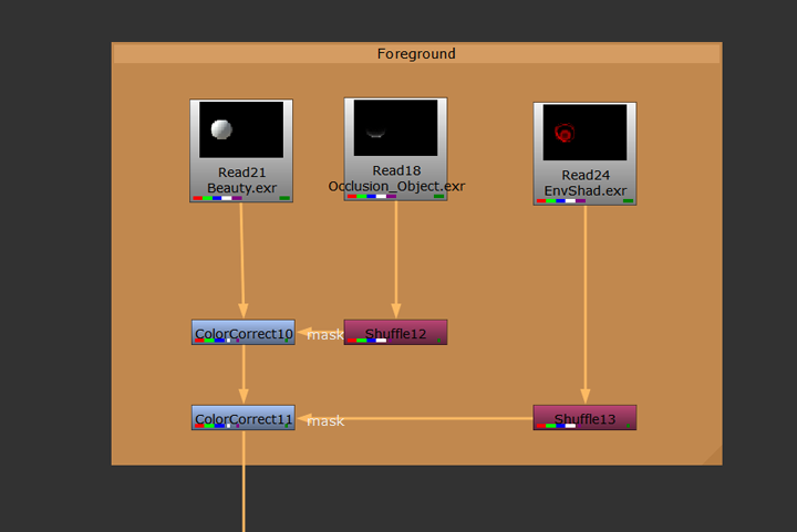
1. This amount of occlusion in an outside of the shadow can be controlled independently of each other by merging the occlusion into the node tree twice.

A Merge (In) Node is used to merge the occlusion within the shadow and a Merge (Out) node is used to merge the occlusion outside the shadow.

The colors have been temporarily changes to green and red to demonstrate the added control in the comp.
4/9/2020
SHADOW OF ENVIRONMENT ONTO OBJECT:
1. In Maya, create a new render layer called PrepforShad. Include the Sphere and ground plane (Double check that the Surface Shader is not repeating the projection by making sure that the Camera Projection Attributes is set to Match Camera Resolution in the Attribute Editor).
2. Make a camera that is in the same location as the key light. This can be done by selecting the key light and looking through selected. Next, go to View - Create Camera from View. Change the focal length of the new camera accordingly so that the project fills the frame. (Note: To view the newly created camera, Shapes must be turned on in the Outliner. When the camera is created a Group Node is created containing a light shape and a camera shape node. The light shape node can be deleted and the camera shape node named accordingly.)
3. Render the frame from this new camera.
4. Paint the shadow shape in Photoshop (shadow red, background black).
5. Create a new layer called EnvironmentShad (Include the Sphere and the ground plane in this layer. Primary Visibility of ground plane - Off).
6. Create a new surface shader and assign it to both the Sphere and the ground plane. In the out color of the shader, link the newly painted image as a projection. Projection type should be perspective and the linked camera should be the key light camera.
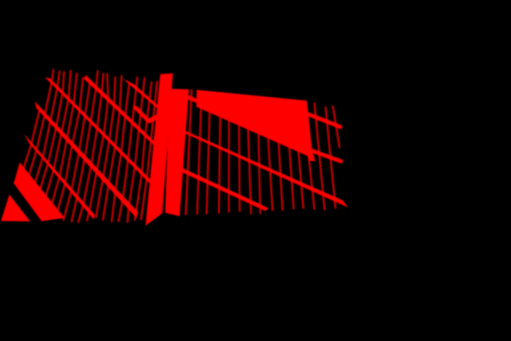
Painted shadow from the perspective of the newly created key light cam.
RenderCam view of painted shadow. Primary visibility of ground plane turned off for render.
Node tree with projected shadow included.
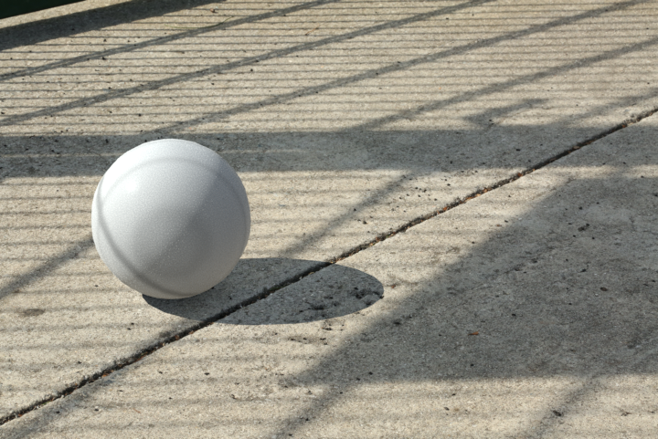
Render of the current comp.
Note that in the render, the shadow projected on the ball from the fence and the shadow made from the key light are combined to create a sort of double shadow. This can be fixed with AOVs.
4/10/2020
AOVs:
For added control, AOV (Arbitrary Output Variables) can be added. In this case diffuse_direct, diffuse_indirect, specular direct, specular indirect, and Z (depth) AOVs were used.
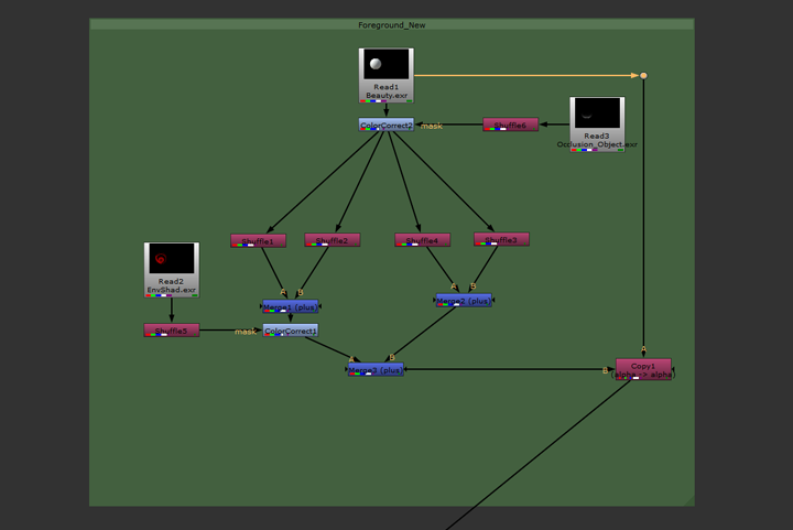

The AOVs are Shuffled into separate channels in the comp for added control. This way the fence shadow can be projected only onto areas of the ball that receive direct illumination. This prevents a double shadow being created on the side of the ball that is already in shadow. After this a Copy Node is used to feed back in the alpha from the original image.
Next a new render layer is created in Maya for the shadow reflection on the ball. All objects from the original shadow layer are included in this new layer however the Primary Visibility of the ground is turned off and turned on for the ball. A layer override is put on the IOR shader of the ball and set to a value of 200 so that the shadow reflection is visible on the ball material. A layer override is also put on the Weight of the Diffuse so there are no diffuse reflections.

Shadow Reflection Layer
Comp tree with added reflection to indirect AOVs
4/13/2020
Various tweaks were made in the comp tree as well as the lighting and shaders to try and match the reference as close as possible. The final comp tree and render can be seen bellow.

After the ball composite was completed, the same base composite was used to integrate other objects into the scene. I chose an apricot obtained from Turbosquid.com and tweaked the textures/shader and composite to obtain the final result bellow.
